M4.x Fuel System Guide
Fuel System Overview
The fuel system on turbo M4.3 and M4.4 cars is a return type with a rising rate fuel pressure regulator (FPR). There is no fuel pressure sensor. With a return type fuel system, there are two fuel lines from the tank to the engine. One line is a high-pressure feed into the FPR and the other is a low-pressure return to the tank. The fuel pump runs at 100% duty cycle all the time, and any unused fuel is returned to the tank.
How the Rising Rate FPR Works
The FPR is a rising rate type, referenced to the pressure in the intake manifold. The purpose of the rising rate FPR is to keep the fuel pressure differential across the injector constant. Since M4.x has no fuel pressure sensor, it assumes that the effective fuel injector size is a constant. Because injector flow rate is directly proportional to pressure, it is the FPR’s job to keep the effective fuel pressure across the injector constant. The tip of the fuel injector sits inside the intake manifold and the other end sits in the fuel rail, so the effective fuel pressure that the injector sees is equal to the pressure in the rail minus the pressure in the intake manifold.
At idle, the intake manifold is under vacuum — usually 22 inHg (−10.8 psi). That means the FPR will reduce the fuel pressure by 10.8 psi. Stock, the base fuel pressure is 3 bar (43.5 psi). At idle, with the vacuum line connected to the FPR, the fuel pressure should be approximately 2.25 bar (32.7 psi). When the turbo is producing boost, the FPR will increase the fuel pressure. So at 10 psi of boost, the fuel pressure should be approximately 3.69 bar (53.5 psi).
Converting Non-Turbo Cars to Turbo
Non-turbo M4.x cars did not come with a rising rate FPR or a return line. For those looking to +T a naturally aspirated car, it is imperative that a return line and rising rate FPR are installed. Without these, the effective fuel injector size will constantly change, and since M4.x has no way to deal with this, fuel delivery will be erratic.
Fuel Pump Duty Cycle and Heat
Since the M4.x fuel system runs the fuel pump at 100% duty cycle all the time, at low engine loads a large amount of fuel will be pumped up to the engine and returned back to the tank. Heat is added to the fuel when it is pumped, which is undesirable because the density of fuel decreases as it gets hotter. This means that the hotter the fuel is, the more of it needs to be injected. This is the primary reason why it is not recommended to oversize the fuel pump — excessively hot fuel can cause the engine to run lean.
FPR Replacement Considerations
It is possible to install drop-in FPRs with a higher rated base pressure. People will sometimes install a 4 bar FPR to increase their effective injector size. However, this is usually not recommended, as the effective size increase is not enough to bridge the gap between the current injector size and the required injector size. Green injectors (440 cc) at 3 bar are not large enough for an 18T, 19T, 20T, etc., and E85. Increasing the fuel pressure to 4 bar increases the flow rate to ~510 cc, but this usually still isn’t large enough for the full potential of the turbo when running E85. A higher base fuel pressure also increases the current consumption and decreases the effective flow rate of the pump.
Unless your power goals are in excess of 600 WHP, there is no performance benefit to replacing the factory FPR. In fact, replacing the FPR with an aftermarket unit only serves to add additional complexity and points of failure.
Fuel Rail Notes
The factory fuel rail is sufficiently sized for 600 WHP. The pre-1995 fuel rails have a smaller inner diameter than the late 1995 rails. The 1998 rails have the largest diameter, but have no provision for an FPR.
1998 x70 Fuel Line Differences
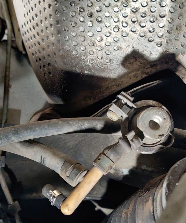
1998 x70s use a slightly different fuel line setup than 850s. On x70s, the FPR is mounted at the firewall and only a single feed line runs from the FPR to the fuel rail. Since the fuel rail is so far from the FPR, a fuel pressure damper is mounted on the rail. The additional metal line running adjacent to the high-pressure feed line, above the timing belt cover, is the vacuum line to the FPR. The vacuum line joins the FPR at a T, joining a small-diameter vacuum line which runs along the water pipe. This is a vent line, designed to allow trapped condensation to melt and evaporate. However, it is a vacuum leak — exactly where a vacuum leak shouldn’t be. We recommend deleting this line and capping it. If trapped condensation is a concern, the cap can be removed during an oil change.
Factory FPR Part Numbers
M4.x had three different types of FPRs:
- 0 280 160 263 — 850s until 1995
- 0 280 160 554 — 850s from late 1995 until 1997
- 0 280 160 557 — 1998 x70s
How to Test Fuel Pressure
If you believe you have an issue related to fuel delivery – an undersized/worn fuel pump, clogged fuel filter or a faulty FPR, testing your fuel pressure can give you a definitive information. By monitoring fuel pressure in relation to manifold pressure, you can determine if fuel pressure is decreasing at times of high fuel demand.
To test fuel pressure, a fuel pressure test gauge can be rented from a local auto parts store, or purchased from Harbor Freight. Most kits come with an adapter for the Volvo fuel rail, a Schrader valve. Unfortunately, the clearance between the Schrader valve on the fuel rail and the throttle cable bracket is quite tight. Without using a right angle adapter, you’ll need to remove two of the three throttle cable bracket bolts and rotate the bracket. If you prefer purchasing the correct adapter, there are two options: this option is the ideal solution, but is a bit expensive. This option is cheaper, but it has no internal valve, so if the fuel pressure tester becomes disconnected while running, fuel can spray in the engine bay.
Testing your fuel pressure at idle or while cranking tells you very little about the health and output capabilities of the pump. At idle, the engine is consuming almost 1/30th what it consumes at full throttle. To fully test fuel pressure, get a passenger and tape the fuel pressure test gauge to the windshield. Have your passenger monitor fuel pressure and boost pressure simultaneously. Ideally, have them record a video showing boost levels and fuel pressure in frame. Drive your car in boost, and make sure that your fuel pressure is always 3 bar greater than manifold pressure. If you see your fuel pressure drop by more than ~5psi under boost, you know you have a fuel delivery issue.
One of the most common issues encountered when installing a new fuel pump is a leak between the new pump’s outlet and the fuel sender assembly inlet. This issue is discussed in our fuel pump listing in our webstore.
Factory Injector Flow Rates
Factory-installed Volvo injectors (all flow rates at 3 bar):
| Color | Flow Rate (cc) | Part Number |
|---|---|---|
| Yellow | 208.6 | 0 280 155 746 |
| Red | 330 | 0 280 155 759 |
| Orange (EV1) | 310 | 0 280 150 785 |
| Orange (EV3) | 329.8 | 0 280 155 831 |
| White | 345 | 0 280 155 766 |
| Light Blue | 345 | 0 280 155 830 |
| Green | 440 | 0 280 155 968 |
The flow rate of blue injectors is usually listed at 4 bar, leading to the incorrect assumption that they flow more than whites. However, at 3 bar they are effectively equivalent to whites.
Oversizing Injectors
Installing injectors which are larger than need isn’t an issue. The tune on the ECU contains a calibration for injector size. When properly calibrated for the specific injectors installed, the engine will receive the correct amount of fuel, regardless of the injector flow rate. Given the quality of modern, high-quality injectors, it’s possible to use 1500 cc or larger injectors without any compromise to idle quality.
Injector Recommendations
For 15G and 16T cars on gasoline, orange injectors are too small — whites or blues are recommended. However, the cost of new green injectors is less than whites or blues, so greens are recommended.
For those running a 15G or 16T on E85, or any stock turbine housing turbo on gasoline (18T, 19T, 20T, 21T, 21TK, 22T, K24), greens are large enough.
Understanding Fuel Trims
Using the oxygen sensor, the ECU has a feedback system to determine whether the engine is running at the correct air-to-fuel ratio (AFR). For emissions reasons, the target AFR during light engine loads is 14.7 parts air to 1 part fuel — put another way, 14.7:1. All of the calibrations related to fueling in the tune flashed to the ECU are configured so that the fuel injectors will deliver the correct amount of fuel to achieve this target AFR. However, since the engine isn’t running under perfectly ideal conditions at all times, the ECU will dynamically adjust the amount of time the injectors spend open so that the target AFR can be met exactly.
Speaking specifically about Motronic 4.4: M4.4 uses three values to keep the AFR as close as possible to 14.7. Those values are the short-term fuel trim (STFT), long-term fuel trim at idle (LTFT_I), and long-term fuel trim at part load (LTFT_PL).
- STFT is the immediate percentage change in the amount of injected fuel being applied at any given moment. This number indicates how much longer or shorter the injector is being held open, based on immediate feedback from the oxygen sensor. If the engine is running lean (less fuel than desired), you’ll see a positive STFT (adding fuel); if the engine is running rich (more fuel than desired), the STFT will be negative.
- LTFT_I is calculated only at idle and is expressed in microseconds. This number is added to, or subtracted from, the fuel injector opening time.
- LTFT_PL is calculated when not idling and not at high engine loads (think cruising). LTFT_PL is a percentage and is multiplied by the injector opening time.
If the AFR stays consistently on one side of 14.7 — either too rich or too lean — the LTFTs will start to intervene. They apply a permanent correction to the amount of fuel injected, in order to keep the range of STFT small. The LTFTs play a balancing act and can take a while to reach equilibrium, if they ever do.
Ideal Fuel Trim Targets
Under perfectly ideal conditions, both LTFTs should be 0 and STFT should vary within ±10%. The STFT is designed to “swing” the AFR slightly above and below 14.7 to prolong the longevity of the catalytic converter, so it won’t ever sit exactly at 0. Now, these numbers are hard to achieve in the real world, so I usually shoot for LTFT_I within ±50 µs, LTFT_PL within ±8%, and an STFT average deviation within ±15%.
Further Reading
For more information on fuel trims:
http://www.obd-codes.com/faq/fuel-trims.php